


Unlock the power of hardware control with Python on the ESP32 and learn how to interact with LEDs, buttons, and buzzers using GPIO pins.
Whether you are just getting started with embedded systems or building your first robot, understanding GPIO programming is foundational. In this guide, we’ll walk you through how to control hardware pins on the ESP32 using Python (MicroPython) — simple, fun, and beginner-friendly!
What Is GPIO?
GPIO stands for General Purpose Input/Output — flexible pins on your microcontroller (like the ESP32) that can be programmed to either:
- Output signals to devices like LEDs and buzzers
- Input signals from devices like buttons, switches, and sensors
Think of GPIO pins as the bridges between your Python code and the physical world.
ESP32 GPIO Basics
The ESP32 board offers many GPIO pins that can be individually programmed. These pins let your microcontroller interact with the outside world — lighting LEDs, reading button presses, making sounds with a buzzer, and much more.
Know more about ESP32 GPIO at the official website
Before we write any code, it’s important to understand how GPIO works.
Understanding GPIO Pins in ESP32
When you program an ESP32, you are actually controlling physical pins on the board. Each pin has a number called a GPIO number.
GPIO means:
General Purpose Input Output
These pins allow the ESP32 to connect with:
- LEDs
- Buttons
- Sensors
- Motors
- Buzzers
Where Do These Numbers Come From?
Look at your ESP32 board carefully. You will see labels like:
- 2
- 4
- 5
- 18
- 19
- 21
- 22
These are GPIO pin numbers.
When we write:
led = Pin(2, Pin.OUT)it means:
- Use GPIO pin 2
- Set it as an output
- Control whatever device is connected to that pin
How to Define Pins in Code
Always follow this order:
- Connect the device to a pin physically
- Use the same pin number in code
Example:
If LED is connected to GPIO 2, write:
led = Pin(2, Pin.OUT)
If the LED is connected to GPIO 5, write:
led = Pin(5, Pin.OUT)Basic Pin Definition Syntax
from machine import Pin

device = Pin(GPIO_NUMBER, MODE)
Modes
Output Mode
Pin.OUTUsed for:
- LED
- Buzzer
- Motor driver
Input Mode
Pin.INUsed for:
- Button
- Sensors
Example 1: LED on GPIO 2
from machine import Pin

led = Pin(2, Pin.OUT)
led.on()
Meaning:
- LED is connected to pin 2
- Pin works as output
- LED turns ON
Example 2: Button on GPIO 4
from machine import Pin

button = Pin(4, Pin.IN)
Meaning:
- Button connected to pin 4
- Pin works as input
Safe GPIO Pins for Beginners (ESP32)
Not all pins are beginner-friendly. Some are used internally.
Use these safe pins for your projects if you are a beginner:
| GPIO | Recommended Use |
|---|---|
| 2 | LED |
| 4 | Button / Sensor |
| 5 | Buzzer |
| 18 | Output devices |
| 19 | Output devices |
| 21 | I2C SDA |
| 22 | I2C SCL |
| 23 | General Output |
| 25 | Analog / Digital |
| 26 | Analog / Digital |
| 27 | Analog / Digital |
| 32 | Analog Input |
| 33 | Analog Input |
Pins to Avoid if you are a beginner
Avoid these unless you know why:
- GPIO 0
- GPIO 1
- GPIO 3
- GPIO 6–11 (used for flash memory)
Using them incorrectly may:
- Stop the board from booting
- Cause random errors
GPIO pins are numbered physical connection points on the ESP32. The same pin number used in wiring must be used in the Python code to control hardware correctly.
LED ON/OFF: First GPIO Experiment
Let’s start with the classic beginner project — turn an LED ON using Python.
What You Need
- ESP32 development board
- LED
- 220Ω resistor
- Breadboard and jumper wires
Wiring
- LED long leg → GPIO pin
- LED short leg → GND
- Resistor in series with the LED
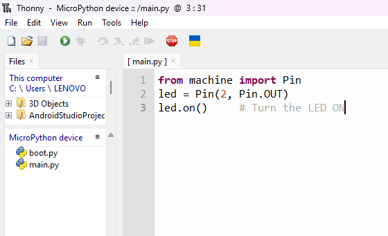
from machine import Pin
led = Pin(2, Pin.OUT)
led.on()     # Turn the LED ON
Run this in Thonny, and your LED lights up! Simple, but powerful — your Python code now controls real hardware.
Check your LED on the breadboard, is it turned on or not?
Adding Delays with Python
To make hardware behavior dynamic, you’ll often need timing and delays. That’s where the time module comes in:
import timeAnd to delay:
time.sleep(1) # Delay for 1 secondBlinking LED: Let’s Add Logic
Here’s a complete example where the LED blinks on and off repeatedly:
from machine import Pin
import time

led = Pin(2, Pin.OUT)

while True:
    led.on()
    time.sleep(1)
    led.off()
    time.sleep(1)
This code makes the LED blink every second. Try modifying the timing to make it faster or slower!
Reading Inputs: Button Control
GPIO can also read inputs — like a button press.
Button Wiring Tip
Buttons can cause unstable readings when left “floating” (unconnected). To avoid this, we use pull-up or pull-down resistors.
Know about the Pull-Up and Pull-down resistors 👇
Pull-Up and Pull-Down Resistors
Pull-Up and Pull-Down Resistors
When we connect a button to a microcontroller like an ESP32, we expect two clear states:
- Button pressed → ON
- Button not pressed → OFF
But in reality, something strange happens.
Sometimes the ESP32 reads:
- random values
- unstable signals
- ON even when the button is not pressed
This happens because of something called a floating pin.
What is a Floating Pin?
A floating pin means:
The pin is not connected to a fixed voltage (HIGH or LOW).
It behaves like an antenna, picking up noise from the environment. So the microcontroller gets confused.
Imagine a Room door:
- Fully closed → CLEAR state
- Fully open → CLEAR state
- Half-open and shaking → CONFUSING state
Floating pins are like that half-open door. We need something to keep the door stable.
That “something” is a resistor.
Pull-Up Resistor
A pull-up resistor connects the pin to a HIGH voltage (3.3V).
This means:
- When button is NOT pressed → pin reads HIGH
- When button is pressed → pin becomes LOW
Why LOW when pressed?
Because pressing the button connects the pin directly to GND.
Simple Flow
Button not pressed
Pin → 3.3V (HIGH)
Button pressed
Pin → GND (LOW)
Pull-Down Resistor
A pull-down resistor connects the pin to GND.
This means:
- When button is NOT pressed → pin reads LOW
- When button is pressed → pin becomes HIGH
Simple Flow
Button not pressed
Pin → GND (LOW)
Button pressed
Pin → 3.3V (HIGH)
Why Do We Need These Resistors?
Without pull-up or pull-down:
- The pin floats
- Random readings occur
- Projects behave unpredictably
These resistors provide a default state.
Which One Should Beginners Use?
For ESP32 and beginner projects:
✅ Use Pull-Up
Because:
- ESP32 already has internal pull-up resistors
- No extra hardware needed
- Easier wiring
Using Internal Pull-Up in MicroPython
from machine import Pin
button = Pin(4, Pin.IN, Pin.PULL_UP)
Now:
| Button State | Reading |
|---|---|
| Not pressed | 1 |
| Pressed | 0 |
Why Not Connect the Pin Directly?
If we connect:
- Pin → 3.3V
- Button → GND
Without a resistor, pressing the button creates a short circuit. The resistor protects the circuit.
Pull-up and pull-down resistors are used to give a stable default voltage to a microcontroller input pin so it does not read random values.
ESP32 has internal pull-ups you can enable directly in code:
button = Pin(4, Pin.IN, Pin.PULL_UP)Now the input is stable:
✔ Not pressed → 1
✔ Pressed → 0
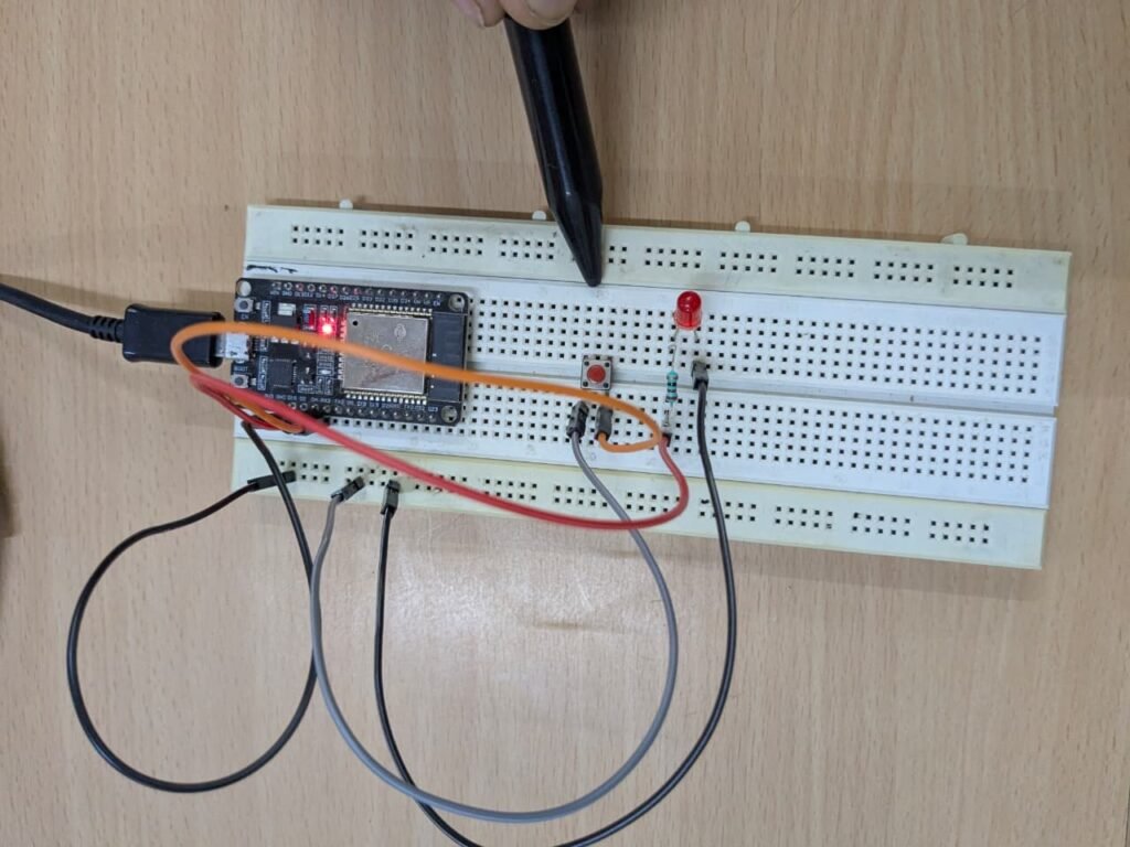
Button + LED Example
from machine import Pin

led = Pin(2, Pin.OUT)
button = Pin(4, Pin.IN, Pin.PULL_UP)

while True:
    if button.value() == 0:
        led.on()
    else:
        led.off()
Press the button and watch the LED turn on!
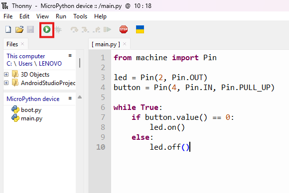
Here, we can see the LED is controlled by the Push button
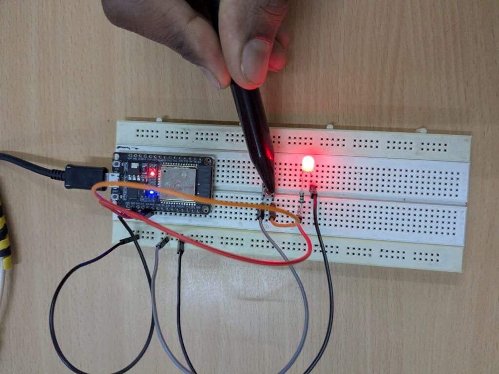
Now try the following one, controlling the Buzzer with a button, just like our mobile phone power button, what happens when we press it one time and what happen on the second time.
Controlling a Buzzer with a Push Button (Toggle Mode)
from machine import Pin
import time

button = Pin(4, Pin.IN, Pin.PULL_UP)
buzzer = Pin(5, Pin.OUT)

buzzer_state = 0      # 0 = OFF, 1 = ON
last_button_state = 1 # button not pressed initially

while True:
    current_state = button.value()

    # Detect button press (falling edge)
    if current_state == 0 and last_button_state == 1:
        buzzer_state = not buzzer_state   # Toggle state
        buzzer.value(buzzer_state)
        time.sleep(0.2)  # Debounce delay

    last_button_state = current_state
In this Article, you learned how to use GPIO pins on the ESP32 to control real hardware using Python. Starting from basic digital output with LEDs to reading button inputs and building toggle logic for a buzzer, you’ve taken an important step into the world of embedded systems.
These concepts form the foundation of all robotics and IoT projects. Almost every advanced system—whether it’s a smart home device, a robot, or an automation project—relies on GPIO control to interact with the physical world.
As you move forward, try experimenting with different pin combinations, creating your own blinking patterns, and combining multiple components in a single project. The more you experiment, the stronger your understanding will become.
⚠️ Common Errors
- LED not glowing — Check LED polarity (long leg to GPIO, short leg to GND) and ensure a resistor (220Ω or 330Ω) is connected in series.
- Button not responding — Verify correct wiring (one side to GPIO, other to GND) and enable internal pull-up in code (
Pin.PULL_UP). - Random button readings — Input pin is floating; use internal pull-up or add an external 10kΩ resistor.
- Buzzer not producing sound — Confirm whether it is an active buzzer; passive buzzers require PWM signal instead of simple HIGH/LOW.
- Buzzer always ON — Logic inverted due to pull-up configuration; adjust code to trigger when button value becomes
0. - Multiple triggers on one press — Add debounce delay (
time.sleep(0.2)) after detecting button press. - Code runs once but stops — Ensure the loop is inside
while True:and there are no indentation errors. - IndentationError in MicroPython — Fix spacing (use consistent indentation, preferably 4 spaces).
- ESP32 resets repeatedly — Check for short circuits or excessive current draw from components.
- File not running automatically after restart — Save the program as
main.pyinstead of another filename. - Wrong GPIO pin used — Match the pin number in the code with the actual ESP32 pin connection.
- Circuit works intermittently — Tighten loose jumper wires and ensure proper breadboard placement.
